


OK .. So, yesterday, i did an OBD1 conversion on a 89 Accord LXi. The swap was made simple by an "already modified" distributor - but honestly, that where the ball stops rolling.
For the swap, ANY OBD1 distributor will work, but the Tabs must be cut off an re-welded (or any other type of method you know for reattaching metal pieces together). From what i understand, the CAM key is no longer at TDC after you realign the Mounting tabs (not first-hand information). Because of this, each Cam Key is going to need to be re-drilled in different spots (from stock), and drilling location is unique to how YOU mounted the Distibutor on YOUR engine. I cannot say "redrill the cam key here, and here" because those holes still might not be where your engine is at TDC. Again, redrilling is going to be unique to your setup, on your own Distributor, depending on how you decided to relocate the timing adjustment/Mounting tabs. DO REMEMBER -- Once you redrill the Cam key, and reset its postion to the correct TDC, firing order is going to be altered!!! (The Stock Firing order, 1, 3, 4, 2 will remain, but will have to be rotated a specific way on the distributor; again - unique to YOUR setup, for how YOU remounted the distributor; use common sense. *See below for more information - *thegreatdane gets credit for this edit). -- During the swap i performed, this issue was not outlined, and i had to use my brain to figure that out for myself. Dont make the same mistake, it WILL cause unnecessary headaches; believe me.
Ok .. after you have successfully setup your distributor, you have arrived at the simpler part.
Run 3 strands of wire to the inside of the car, under the carpet, over to the ECU (under the seat) It would be best if 2 of the wires were shielded, preventing unnecessary radio frequencies (emitted by the wires) from interfering with surrounding Audio equipment wires (such audio wires would have to be in VERY close proximity for this to happen); so using shielded wire is not THAT serious. -- For reasons of making it easier to identify, and repair broken wires later, i would recommend running a Blue, Green, and Yellow wire. Once in the engine bay, run these wires to the Distributor.
Ok .. Distributor wiring. Cut off the Plug from the OLD distributor, because we are going to reuse the Plug, and get ahold of an 8 pin Distributor plug for your NEW OBD1 dist. as well (Harness Side) -- we are going to make a Conversion Harness.
Here is the pinout -- OBD1 Plug >> OBD0 Plug (4Pin)
Orange to Orange
Orange Blue to Orange Blue
White to White
White Blue to White Blue
Simple enough -- Plug it in!
Now, the BLUE/GREEN wire on the OBD 1 side, connect that to the GREEN wire we ran from in the car, and connect the BLUE/YELLOW wire to the BLUE wire we ran from in the car. Simple Pinout form of what i just said is below:
OBD1 Dist Plug >> Wires we ran from in the car
Blue/Green to Green
Blue/Yellow to Blue
Still with me?
On that SAME 8 pin plug that we have made all these connections so far (6 to be exact), there are still 2 wires. Both of these wires will vary in color depending on what car the Distributor came from. I will outline the most common.
*The yellow/green wire is the SAME wire as white. --- white and yellow/green are the SAME thing.
*The black/white wire is the SAME wire as green. --- green and white/black are the SAME thing.
--- Distributors WITHOUT Black/White (green) wire coming out of the Dist, have an INTERNAL coil, and you do not need to run an external coil on your car -- .. your life is made simple. If your Dist has a 7-pin plug instead of the 8 pin, you have an INTERNAL Ignition coil, so disregard the External Coil connection proccess.
OK! ... connect the yellow wire we ran from inside the car, to the yellow/green (or white) wire on the dist.
And finally, (for external coils), run the black/white (or green) wire from the dist, to the NEGATIVE side of your ignition coil.
In Pinout style -- OBD1 plug >> Wires we ran from in the car:
Yellow/Green (white) to Yellow
Black/white (green) to the Negative side of your ignition coil.
........
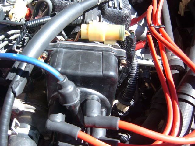
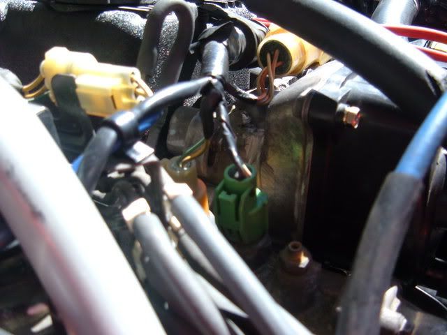
--There is also a 2 pin plug on the distributor. This plug has a Blue wire, and a Black/yellow wire. Find an original Harness plug, cut it off, and attach it to the blue wire, and black/yellow wire where your original Ignition Coil used to be.
Blue to Blue
Black/yellow to black yellow
-- plug in the Capacitor
Thats all plug it in! Your distributor is NOW wired up, and ready for action.. only a few steps left!
............
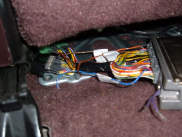
This is where it gets tricky. THE ECU!
You CAN, and in fact need, go out and buy a OBD0 to OBD1 conversion harness, don't trust that it is correct!! ... The conversion harness which i was intending to use, actually came out of a running Car, the same exact car for that matter, but i still found that the pinout was incorrect. Fortunately for me, i had a harness which i had made, that had the Stock OBD1 wire colors still intact, and was also pinned out correctly
When you buy a harness MAKE SURE that these pins are correct, and going to the appropriate wires -
Plug in your jumper harness and trace back the Orange, Orange/Blue, White, White/Blue, wires on the OBD0 C-plug, and make sure that they correspond to the correct pins on the ECU! The pinout is below:
OBD1 Side:
B11-CYP P CYP(#1 piston position) -P Orange, CYP sensor input, n/a
B12-CYP M CYP -M White, CYP sensor signal, n/a
B13-TDC P TDC(top dead ceter) -P Org/Blue, TDC sensor input, n/a
B14-TDC M TDC -M Wht/Blue, TDC sensor signal, n/a
B15-CKP P CKP(crank position) -P Blu/Green, CKP Sensor input, n/a
B16-CKP M CKP -M Blu/yel, CKP Sensor signal, n/a
-- So, what im saying is - the orange wire from the (OBD0) C-Plug, should go to the pin where the Orange wire should be on the ECU (B11) - If it is NOT --- then REPIN it!! You MUST, if you want the car to start. --- DO the same for the 4 wires i posted above.
Ok! Good! Now ... Do you recall the 3 wires we ran into the car (the 2 sheilded wires, and the other)?
You are going to need to connect the Green wire to Pin B15 (OBD1 harness), and connect the Blue wire to Pin B16 (OBD1) harness ... Again, if you forget to do this, then you are SOL and will be stuck with a NO start situation.
And at last --- the Yellow wire we ran. Connect this wire to pin A21, AND A22 on the OBD1 ECU Plugs.
A21-ICM Yel/Grn, Ignition Control Module output signal, About 10V KOEO
A22-Igniter, same as A21
............
OK .. the firing order, in the case of my conversion, was NOT the same as stock. Like i said, after redrilling the Cam Key, the firing order had been adjusted 90* from stock. After figuring this out, and readjusting the Firing order (by swiching moving the wires), the car started up beautifully.
STOCK firing order (looking at the Dist Cap) is:
1 3
2 4
The MODIFIED Cam Key firing order (while looking at the Cap) is:
2 1
4 3
Keep this in mind for if/when you need to troubleshoot your OBD swap. The best way to see which where Cyl #1 is on your engine after redrilling an d mounting the Distributor is to Take off the Cap, and rotate the Engine to (cyl #1) TDC. Take note of where the Rotor is facing, and that is your new Number one plug on the Cap. The firing order is 1, 3, 4, 2, going CLOCKWISE from that plug.
-----
Well, thats it, Plug in your ecu, and see if your car starts!!
I have NO (helpful) pictures now, but hopefully i will soon. What would you like to have pictures of, what would help you understand what i have written?
TaDa!
In the above picture, this vehicles firing order is INCORRECT! Please dont mimic it, your car will not start.
Re-Chipped his ECU ---


 Reply With Quote


Bookmarks