
if you could combine p06 timing with p75 fuel i think it would work pretty well. But it doesnt really matter if your running Crome Pro with autocorrect :-)


if you could combine p06 timing with p75 fuel i think it would work pretty well. But it doesnt really matter if your running Crome Pro with autocorrect :-)

rofl well obviously not but hmm so maybe this p06 will be of some use afterall.
dead white and blue

I was looking thrugh my pictures and found this diagram I had made for ericw to try and troubleshoot a problem he was having. Its basicly a quick diagram of the wiring for the obd1 distributor when wired into the accord harness.
Rudelude Please compare to your notes and if evrything is ok you can add it to your original post.
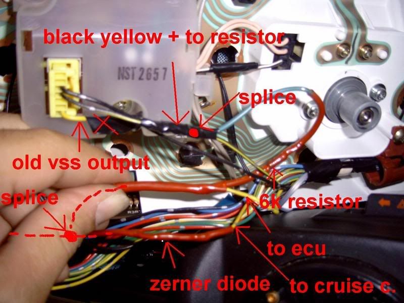
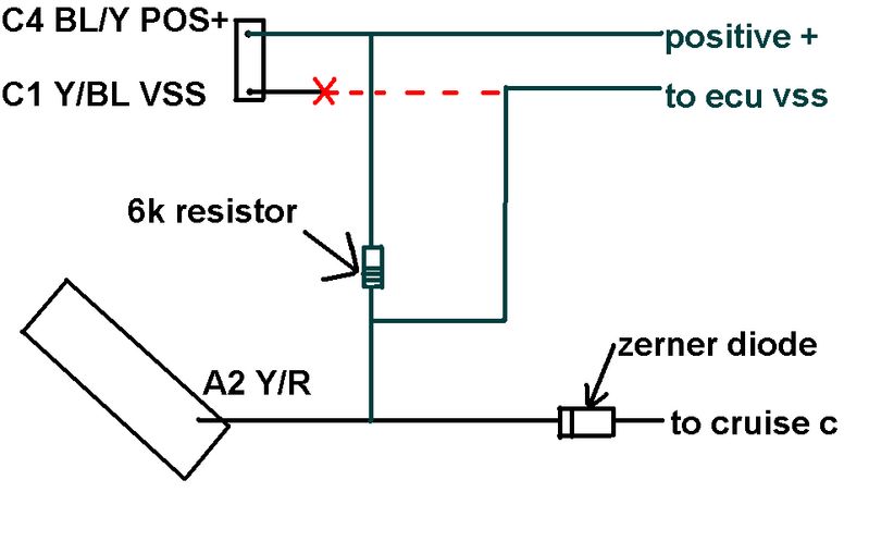
These next couple of pictures are for the vss issue. If you do not get a cel dont worry about it. but if you do you must use the speed pulser output from behind the gauge cluster to the ecu vss input. You must use the speed pulser instead of the stock accord vss signal. Once you swap the speed pulser output to the vss wire behind the gauge sluster you must get a 6k resistor to wire in to get the correct polarity vss signal.
Anyway heres a couple of pics that will ease the install.
Last edited by guaynabo89; 11-06-2007 at 09:33 AM.
Did anyone ever figure out if a EF Civic DX or Si conversion harness was used? They are both a bit different.
I'm going to guess the Si.
Last edited by MoonScryer; 11-21-2007 at 05:30 AM.
I am the wrath of the server you curse and the demon of the directory you cry about - making life hell for users, one deleted file at a time.
there is no dx conversion harness per say. they are all for mpfi (si) if you have a dx, you have to convert to mpfi first (4 injectors) then use the conversion harness. you can get the harness for cheap off ebay, like $50 but the connectores that go into the ecu are real cheap and chew up easly. if you dont plan on removing your ecu alot they will be fine. or you can always depin it and put on the factory connectors you cut out of another car.
on a side not, anyone who needs a modified obd1 ecu hit me up, i got them by the boatloads, chipping them daily
Style Quality Uniqueness And Design
S.Q.U.A.D. Engineering
www.squadengineering.com
http://www.facebook.com/squadengineering
I have a question about the "redrilling cam key alters your fire order" (or at least the order the plug wires go onto the dizzy).
It's my understanding that when you redrill the key, it lines up so that distributor points to cable 1 while the engine is at #1 TDC. If the dizzy's rotor still spins the same direction, and starts out at the same spot, how can the other 3 cylinders not also be in line?
I plan to take my dizzy and stake the base next to the shaft that holds the cam key, at the existing holes in the key, which basically marks where the pin should be when the the engine is at #1 TDC. Then, mount the dizzy, turn the engine until it's at #1 TDC, pull the dizzy out, and stake the key next to the two stakes I made before. The stakes on the key represent where the pin that holds the key on should be at #1 TDC, and when the key is mounted with the pin at that position, distributor and engine should hit cylinders at the same time, plus or minus a few degrees to adjust for by rotating the dizzy a little bit.
If there is something wrong with this line of reasoning, would someone please point it out and explain to me how I'm wrong?
The Wheel of Time turns and Ages come and go, leaving memories that become legend. Legend fades to myth, and even myth is long forgotten when the Age that gave it birth comes again
~Robert Jordan's The Wheel of Time series
the 4th gens firing order is different than ours. Thats why you have to get the cam key redrilled.
The firing order isn't different. You just can't mount the 4th gen distributor in its TDC position on the A20 with out interference issues. That is why the cam key must be re-drilled. So that TDC on the motor matches TDC on the distributor in its mounted position.
Concerning guaynabo89's diagram above, I have a quick question about the cable that goes from our distributor to the left plug on the coil. That particular stretch carries the two wires that go on the small plug in the new dizzy, the blue tach wire and the black/yellow coil positive. It also carries a third wire, which I'm not sure of and didn't have my manual with me to see what it is.
This third wire is all black I believe, and connected to the casing of our old dizzy unshielded, as if it were a ground. However, following the other end, it goes past the coil, through the radio condenser (fancy square capacitor) and then dives underneath the fusebox.
Generally anything coming from the fusebox is positive (you can get ground almost anywhere in a car), but it appears to ground the dizzy. My final answer (in the form of a question) is does this wire represent any of the wires in the diagram, and if so, which one? I'm hoping for the green coil negative.
The Wheel of Time turns and Ages come and go, leaving memories that become legend. Legend fades to myth, and even myth is long forgotten when the Age that gave it birth comes again
~Robert Jordan's The Wheel of Time series
I thought that sounded weird. A) I've been told all hondas in this class fire 1342, and B)if swapping the wires fixed it, what if someone's rotation wasn't anywhere near 90 degrees (or multiple thereof). I guess all will be settled when I get my key back from the drill press.Originally Posted by EricW

Speaking of which, does someone know offhand, on the stock dizzy, when at #1 TDC, which piston is the rotor pointing at? I know our timing is supposed to 25-15 (I'm guessing, I could be 10 - 20 off) degrees BTDC, but that's not the same piston?! We want to fire near BDC (not BTDC, bottom dead center), surely time from spark to peak ignition pressure isn't over 90 degrees?!
I'd like to think everyone who pitches into to these documents, especially with the pretty Paint/Gimp diagrams.
The Wheel of Time turns and Ages come and go, leaving memories that become legend. Legend fades to myth, and even myth is long forgotten when the Age that gave it birth comes again
~Robert Jordan's The Wheel of Time series
Since I no longer have radio condenser, and I didn't go look at the car, I'm looking at the diagram in the Honda manual. The negative wire for the radio noise condenser attaches to a screw on the ignitor for a ground and the positive side connects to the black/yellow wire(s). The radio noise condenser/wires are not used in the OBD1 swap. If i remember right the obd1 ignitor has one built in.
The black/yellow wires attach to the coil positive and the green wire from the ignitor in the distributor is the negative coil wire.
I'll go look at the car later to verify all of this but it may be hard since I'm not running the stock ignitor either since I'm using the msd system and used an ignitor bypass which I built.
im too lazy someone make me a kit i'll buy it haha soldwiring makes me angry, replacing stuff works better for me.
-Harvey
Coil Diagram
Terminal A comes from the ignition switch (positive), so I assume that "Coil Negative" is terminal D?
And then I suppose terminal C is coil positive?
The Wheel of Time turns and Ages come and go, leaving memories that become legend. Legend fades to myth, and even myth is long forgotten when the Age that gave it birth comes again
~Robert Jordan's The Wheel of Time series
Is the heater circuit on your 4-wire o2 sensor bad, or did you hook up to one of the existing 1-wire sensors?
The Wheel of Time turns and Ages come and go, leaving memories that become legend. Legend fades to myth, and even myth is long forgotten when the Age that gave it birth comes again
~Robert Jordan's The Wheel of Time series
quick question? is a p27 chipable??
and i have Searched the web but cant find.. a list of ALL honda ECUs OBD number and whether they are chipable
chipable ecu's
USDM, EDM, or JDM
Non-VTEC
P05
P06
P09
P1K
P27
P29
P54
P74
P75
PR4
VTEC ECUs
P08
P28
P30
P61
P70
P72
P91
PR3
I guess its easy. I used Boomslang MPFI OBD0 to OBD1 conversion harness.
I used this pinout to double check everything on it http://carotman.no-ip.com:8888/perso...0A3pinout.html
then i came up with this
OBD1->OBD0 - Function
A01 ->A01 - #1 injector
A02 ->A07 - #4 injector
A03 ->A03 - #2 injector
A04 ->N/C - VTEC solenoid Valve
A05 ->A05 - #3 injector
A06 ->N/C - O2 Sensor Heater Control
A07 ->A6&A12 - Fuel Pump Relay (FLR1)
^^boomslang A07 ->A12&14
A08 ->N/C - Fuel Pump Relay (FLR2)
A09 ->A11 - EACV
A10 ->N/C - EGR solenoid valve
A11 ->N/C -
A12 ->N/C -
A13 ->B06 - Check Engine Light (MIL)
A14 ->N/C -
A15 ->B01 - A/C Clutch Relay
^^boomslang A15 >B02
A16 ->N/C -
A17 ->N/C -
A18 ->N/C -
A19 ->N/C -
A20 ->B02 - Purge Control Solenoid Valve
^^boomslang A20 ->A06
A21 -> run a wire to dizzy - Igniter Power Source (IGP1)
^^boomslang A21 ->15&17
A22 ->N/C - Igniter Power Source (IGP2)
A23 ->A02 - Power Ground (PG1)
A24 ->A04 - Power Ground (PG2)
A25 ->A13 - Main Relay IGP1 (IG Power)
A26 ->A18 - Logic Ground (LG1)
A27 ->N/C -
B01 ->A15 - Power Source (IGP2)
B02 ->A16 - Logic Ground (LG2)
B03 ->N/C -
B04 ->N/C - Service Check Connector
B05 ->B08 - A/C Switch (ACS)
B06 ->N/C -
B07 ->N/C -
B08 ->N/C - P/S Pressure Switch
B09 ->B13 - Starter Switch Signal (STS)
B10 ->B18 - Speed Sensor
^^boomslang B10 ->B16
B11 ->C01 - CYL Sensor
^^boomslang B11 ->B08
B12 ->C02 - CYL Sensor
^^boomslang B12 ->B10
B13 ->C03 - TDC Sensor
B14 ->C04 - TDC Sensor
B15 ->run shielded wire to dizzy- Crank Angle Sensor
^^boomslang B15 ->C01
B16 ->run a shielded wire to dizzy- Crank Sensor
^^boomslang B16 ->C02
D01 ->A17 - Back Up Fuse
^^boomslang D01 ->B01
D02 ->N/C - Brake Switch
D03 ->N/C - Knock Sensor
D04 ->N/C- Service Check & Ignition Timing Connector (SCS)
D05 ->N/C -
D06 ->N/C - VTEC Pressure Switch
D07 ->N/C - Data Link Connector
D08 ->N/C -
D09 ->B14 - Alternator
D10 ->B19 -
D11 ->C07 - Throttle Position Sensor (TPS)
D12 ->N/C -
D13 ->C06 - TW Sensor
D14 ->C16 - O2 Sensor
^^boomslang doesn't run this connection but they provide wires to use an obd1 o2 sensor
D15 ->C05 - Intake Air Temperature Sensor
D16 ->N/C -
D17 ->C11 - MAP Sensor
D18 ->N/C -
D19 ->C15 - Sensor Voltage (VCC1)
D20 ->C13 - Sensor Voltage (VCC2)
D21 ->C14 - Sensor Ground (SG1)
D22 ->C12 - Sensor Ground (SG2)
The pinouts in bold are the ones you have to rearrange. Underneath them in bold i show how boomslang ran them which is wrong and needs to be arranged like the top one.
I/H/E, B16 mani, delta 272, OBD1....etc
http://technet.ff-squad.com/wiring.obd1.htm
Obd1 harness/ecu pinout to double check your wires.
Accord obd0 pinout
http://carotman.no-ip.com:8888/perso...0A3pinout.html
Something I thought should be added to the first post to help.
Would SCSI cables be an option if you wanted to make custom ecu connections? I have a few old printer ones laying around, and they are about 4' to 6' long.
- llia
what gauge wires should be used for the 3 you have to add. crank position(2) and ignitor.
can all 3 be ran in a strand shielded together, or should the 2 crank wires be shielded and the 3rd be separate?
Style Quality Uniqueness And Design
S.Q.U.A.D. Engineering
www.squadengineering.com
http://www.facebook.com/squadengineering
Better safe them sorry I would say shield them. As far as size go's they use a 16g or 18g stock I think. So I wouldn't go bigger then 14g I think that would be over kill.
Sent from my SPH-L720 using Tapatalk
For my shielded wire I went to lowes, got the 4wire shielded bundle, and used that. I think its like 16g wire.
Same thing I did.
Sent from my MB860 using Tapatalk 2
This is for Code 17 or VSS signal.don't know if it works for everybody but it worked for me on my 86. I swap the little white box from a 89 cluster to my 86 cluster.the only difference between the little boxes was the 89 has one single wire coming off of it that the 86 did not have. I give the credit to Rendon L-xi
Last edited by Shane86; 08-12-2017 at 11:50 PM.
A closer look at the Distributor wiring. Left side is A21 B15 and B16 will be your shielded wire.the green wire under A21 is for external coil distributor only. And the four wires on the right side of the connector you just match the four colors up
Last edited by Shane86; 05-24-2018 at 07:11 PM.
 Posting Permissions


 Reply With Quote
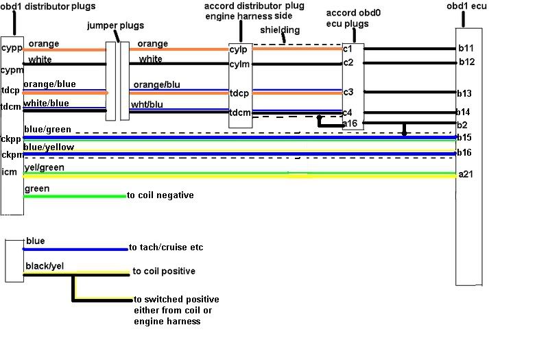


Bookmarks