


As some of you may know, i am building a UV gauge setup. Now, i want to be sure that im doing all the wiring correctly before i go to install it into the car. What i plan to do is build a gauge test harness.
Heres what i have: I bought a DC 12v blacklight with a cigarrette adapter and an AC/DC converter, which i have successfully used to prepare my gauges. Now im in the install phase.
Im going to the junkyard today to grab the gauge harness out of the dash of a car. Thats the three plugs that go into the back of the gauge cluster.
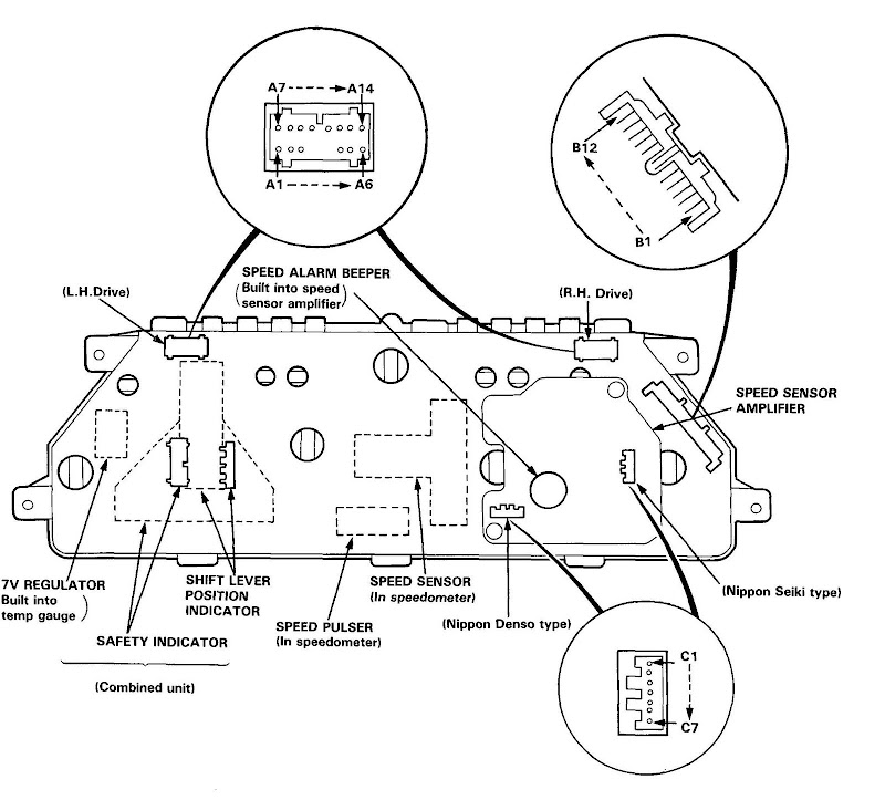
Heres a picture of what im dealing with.
and the pinouts.
Alright now im not sure if im gonna get the dimmer circuit wired, but here are my plans for now. Im chopping the cigarrette adapter off the end of the blacklight wiring, and im going to use that as my positive source. i plan to solder the blacklight into where the stock gauge light goes.
Unused wires: A1, A2, A3, A9, B2, B5, B6, B7, C1, C2, C3, C4, C6, C7
These are the wires that go to the dimmer switch circuit, gauge input, and unused warning lights.
Ground wires: A8, B8, C5
Now two of these are grounds for things im not wiring, but im putting them in just in case.
Positive wires are everything else.
Heres my question for the electrical gurus. Is this gonna work? An even better question is is this gonna work without the dimmer switch? i dont think it will be too difficult to get the dimmer switch wired if its necessary, but im just curious.
Oh and for those wondering why im wiring the warning lights its just to make sure that they are working. I pulled this cluster out of a junkyard car and want to be sure that they are working. Im also working with some LEDs.


 Reply With Quote

Bookmarks