alright ive got all the information together for a writeup but your needs are a little different. I will give you wire color of under the hood connections of what connects to what. also was your conversion jumper a special made for the 3rd gen accord or is it a standard obd0 - obd1 conversion jumper? this will give me a better idea of how to connect your system up.
Legend_Master - if you have a custom jumper harness, you may not have to do some of these steps.
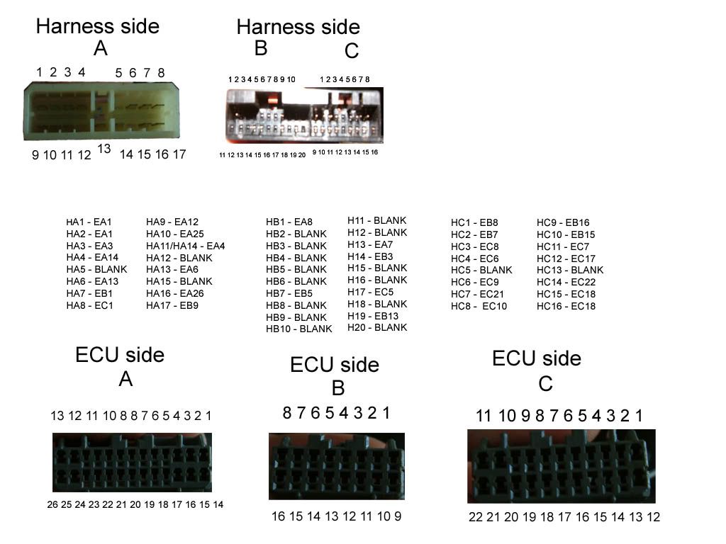
in the mean time here is the ecu pinout diagram of the obd0 connectors.
I will do this in phases. ecu connections then instrument cluster, dizzy, alternator.
the following steps will walk you through a re pin of the 3rd gen harness to connect a OBD-0 Vtec ECU like the JDM Pr3-j50/j51 to the harness and have it running in a couple of hours.
Also this will prep your wiring harness for any off the shelf OBD-0 to OBD1 Acura Integra jumper harness.
NOTE: If you look at the connector from the rear, the top left is pin 1 the wire below is pin 2....so on and so forth.
ECU Plug A
a1 - injector 1 (brown)
a2 - main relay (black)
a3 - injector 2 (red)
a4 - main relay (black)
a5 - injector 3 (blue)
a6 - main relay (green with black stripe / same as a12)
a7 - injector 4 (yellow)
a8 - bypass control solonoid (white)
a9 - NOT A REAL PIN
a10 - EGR lift solonoid (red)
a11 - EACV control (black with blue stripe)
a12 - Main relay (green with black stripe / same as a6)
a13 - power feed to the resistor box (Yellow with black stripe / sam as a15)
a14 - NOT USED
a15 - power feed to the resistor box (Yellow with black stripe / sam as a13)
a16 - Engine ground for ECU (Brown with black stripe)
a17 - Fused ECU power (White with yellow stripe)
a18 - Engine ground for ECU (Black with red stripe)
Modifications and pin locations notes and what to do with wires.
for PLug A marked in RED
All of the wires for ECU plug A can be located in the engine bay driver side female connector, except where noted differently.

a1 - injector 1 (brown)
connect to injector
a2 - main relay (black)
Tap wire and add a connection to direct ground. Without Main relay will not fire up and fuel pump will not run. see picture

a3 - injector 2 (red)
connect to injector
a4 - main relay (black)
a5 - injector 3 (blue)
connect to injector
a6 - main relay (green with black stripe / same as a12)
Remove pin from plug and move it to pin location 14. see picture

a7 - injector 4 (yellow)
connect to injector
a8 -
connect to Vtec Solonoid. you can utilize the stock wiring harness in the car. the white wire is located in the main plug that connected the vaccume box on the firewall. see picture

a9 - NOT A REAL PIN
a10 - EGR lift solonoid (red)
not used
a11 - EACV control (black with blue stripe)
Connect to EACV.
NOTE: The EACV also requires a direct fused link to 12v This will be the rather large black wire with yellow stripe located in the female chassis side harness connector.
a12 - Main relay (green with black stripe / same as a6)
a13 - power feed to the resistor box (Yellow with black stripe / sam as a15)
this connects directly to the resistor pack for the fuel injectors. NOTE: when using high impedance injectors you will connect this wire directly to the positive side (red wire with black stripe) of the fuel injectos.
a14 -
pin a6 (green wire wit hblack stripe) is to be placed here.
a15 - power feed to the resistor box (Yellow with black stripe / sam as a13)
a16 - Engine ground for ECU (Brown with black stripe)
Ground to engine
a17 - Fused ECU power (White with yellow stripe)
remove from plug tape up and discard see picture

a18 - Engine ground for ECU (Black with red stripe)
Ground to engine
I will cover the other ECU plugs when i get off work, takes alot to put it in so much detail.


Originally Posted by Importordomestic


 Reply With Quote


Bookmarks