Results 1 to 11 of 11

Thread: Simple Wiring Diagram for Winking / Sleepy Eyes

  1. #1
    DX User
    Join Date
    Apr 2012
    Posts
    96

    Simple Wiring Diagram for Winking / Sleepy Eyes

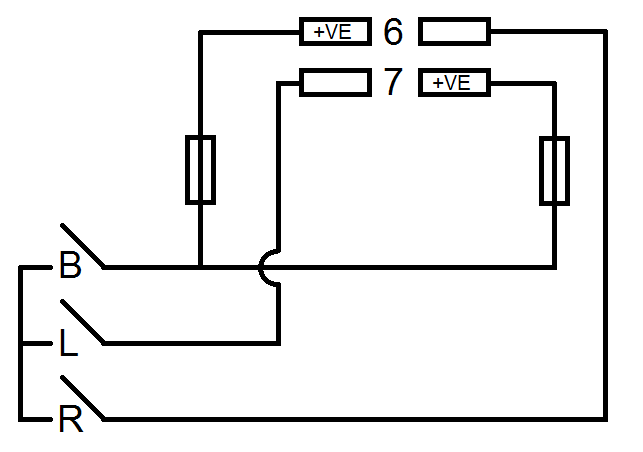
    I have done this on my car where I can make each light "wink" independently, or I can make the eyes sleepy, drunk, whatever, and thought I'd stick a thread up with a nice, simple wiring diagram and a video and some photos of what the final results can be. BE WARNED - SLEEPY EYES WILL MAKE YOUR CAR LOOK DEPRESSED!!!! I did it as my car has the nickname of "Marvin" after the paranoid android, and sleepy eyes make it look even more like him!


    VIDEO


    These are the under dash fuses, 6 and 7, for the right and left retractor motors respectively. Please do note, that the left side of fuse 6 is positive, and the right side of fuse 7 is positive!

    On the diagram, B = Both, L = Left and R = Right.


    Parts required:
    3x switches (standard on / off switches, with 2 terminals)
    4x male blade terminals
    10x female blade terminals
    And some speaker wire
    Last edited by Crazy_C; 06-06-2012 at 02:29 PM.


  2. #2

    King Peetis's Avatar
    Join Date
    Oct 2007
    Vehicle
    1988 Honda Accord LXi hatchback--white with maroon
    Location
    Atlanta, ga
    Posts
    499

    Re: Simple Wiring Diagram for Winking / Sleepy Eyes

    This is something I have always wanted to do to my car. Can you supply detailed DIY info and what is required to control the lights for wink, sleepy and full up or full down. Me and electricity dont get along so please make it simple.

  3. #3
    DX User
    Join Date
    Apr 2012
    Posts
    96

    Re: Simple Wiring Diagram for Winking / Sleepy Eyes

    No worries. Hope this will help.

    You'll need:

    3x switches of your choice of style. I just went for some normal long toggle switches, but you can go for whatever you want, as long as they're an ON-OFF design (ie not push-to-make switches)

    You'll also need 4x male blade terminals to go in the fuse box instead of the fuses, and you'll need 10x female blade terminals to connect to the switches (assuming they use blade terminals to connect) and to wire the fuses in line.

    The last thing you'll need is some speaker wire. I suggest speaker wire as it runs nicely in pairs (one pair of wires for left, and one pair for right) and speaker wire is generally marked on one side of the wire too.


    STEP 1:

    Open your hood, remove the cover on your fuse box, and remove the fuses for the left and right retractor motors (fuses 6 & 7)


    STEP 2:

    Take 2 lengths of speaker wire, long enough to reach from the fuse box to inside the car where you want the switches to go. Put the male blade terminals on the end of the wires, and plug them into the fuse locations.

    Make sure that the marked side of one length of speaker wire goes on the LEFT side of the R RETRACTOR fuse, and the marked side on the other length of speaker wire goes on the RIGHT side of the L RETRACTOR fuse. These marked wires will be POSITIVE


    STEP 3:

    Run your speaker wire into the compartment of the car. You'll need to find a grommet or a hole to run it through, there are a few around.

    Find where you are going to fit your switches, you will need 3 of them, and get them installed ready to wire up.


    STEP 4:

    The marked side of your wires, the positive side, will need to have the fuses run inline with them. So on the marked wires, cut a length off (but leaving the unmarked side uncut) and put a female blade terminal on the end of the remaining bit of marked wire, as well as the bit you just cut off. Connect these terminals up to each end of the fuse, so the original fuses are still in the wiring for the motors.

    With the lengths of marked wire that come off from the fuse, you will need to connect these two wires together and put a female blade terminal on the singular end.

    Put a female blade terminal on the ends of the unmarked wires


    STEP 5:

    You will need to get an extra bit of speaker wire as well, about 3" long. With this, you will need to separate the wires about half way down the length. On the ends of the separated wires, you will need to put a female blade terminal on. On the end where both wires are still together, you will also need a single female blade terminal connecting to both wires.


    STEP 6:

    Here's the fun part, wiring the switches!!

    The marked wires that go from the fuses to one female blade terminal needs to be connected to one side of one switch (if the terminals on the switches are marked, connect this to the power terminal, if not, it doesn't matter).

    The unmarked wires that go from the fuse box need to go to one of the terminals on each of the other two switches. If the terminals are marked, connect them to the side that doesn't say power.

    The extra bit of wire that 2 terminals on one end, and one terminal on the other, this needs to connect the remaining terminals up between the switches. If the terminals on the switches are marked, it should be connected to the power terminal on the switches with the unmarked wires, and on the switch with the marked wires, it should be connected to the other terminal to power.


    STEP 7:

    Quite simply, is test it out. You will have one switch that will stop both lights (this is the one that had the marked wires going to it), and you will have one switch that will stop the left, and one that will stop the right lights. If the switch that controls both lights is off, then neither of the other switches will work.


    STEP 8:

    Find a friend to video you playing with your lights, like I did. Then post that video on YouTube and link it on here


    You will then have 3 switches. To make the car wink, put your lights up with the normal switch. If they don't go up, make sure none of the control switches are active. When the lights are up, flick one side light switch, and just tap your normal light up/down button twice as if you were just putting your lights down and then straight back up again. Your car should have just winked

    To give the car sleepy eyes, put your lights up, hit the switch to lock both lights, press the normal button as if you were going to put your lights down, and they should not move. On the control switch for both lights, quickly flick it from one side and then back again, and your lights should have dropped about half way and then stopped. You now have a very sad looking Honda
    Last edited by Crazy_C; 06-06-2012 at 03:00 PM.

  4. #4
    3Geez Veteran lostforawhile's Avatar
    Join Date
    Dec 2002
    Vehicle
    86 hatchback, 1990 Lincoln Towncar
    Location
    nowhere GA
    Posts
    15,401

    Re: Simple Wiring Diagram for Winking / Sleepy Eyes

    you do understand if one of those speaker wires shorts it's going to melt, the input side of those fuses is directly off of the 70 amp main bus. I understand the idea but use real wire

  5. #5
    DX User
    Join Date
    Apr 2012
    Posts
    96

    Re: Simple Wiring Diagram for Winking / Sleepy Eyes

    Yea, this is thick insulation speaker wire. I didn't mean to use the cheap ass speaker wire you get for $1 off eBay. The speaker wire I used is high quality for professional applications.

    As I have friends who run a car audio company, I generally use lengths of speaker wire for most wiring, always the high quality stuff, and I've never once had any issues or problems.


    Obviously though, the correct electrical wire, rated to 70A+ would be best, but as this was laying around, and it's high quality, this is what I used.

  6. #6
    3Geez Veteran lostforawhile's Avatar
    Join Date
    Dec 2002
    Vehicle
    86 hatchback, 1990 Lincoln Towncar
    Location
    nowhere GA
    Posts
    15,401

    Re: Simple Wiring Diagram for Winking / Sleepy Eyes

    Quote Originally Posted by Crazy_C View Post
    Yea, this is thick insulation speaker wire. I didn't mean to use the cheap ass speaker wire you get for $1 off eBay. The speaker wire I used is high quality for professional applications.

    As I have friends who run a car audio company, I generally use lengths of speaker wire for most wiring, always the high quality stuff, and I've never once had any issues or problems.


    Obviously though, the correct electrical wire, rated to 70A+ would be best, but as this was laying around, and it's high quality, this is what I used.
    you need to have the fuses as close to the fuse box as possible to have the shortest lengths of unfused wire possible also speaker wire is fine for inside the car but it's not designed for heavy amperage loads and is not designed for the heat and other conditions under a hood. if the fuses were at the fuse box the wires would be carrying 15 amps but since the wires are tied directly into the bus the next fuse is the 70 amp main battery fuse

  7. #7
    DX User
    Join Date
    Apr 2012
    Posts
    96

    Re: Simple Wiring Diagram for Winking / Sleepy Eyes

    I actually just clicked on what you were saying about the 70A too, wasn't fully on it last night when I replied. If there was 70A where the fuse was, the 15A fuses would pop instantly. All the wires see 12V and the current draw is dependant on whatever the wires are controlling, in this case, the retractor motors which are 15A max, hence the 15A fuses for them. The only thing that isn't ideal is the fact that the fuses are quite a distance from the fuse box, but as I was just using spade connectors to wire them in, and not a proper inline fuse holder, I opted to have them inside the car. You could say the same thing about amp wiring kits that have a 30 or 40A fuse and the amps just have a 30A fuse. The next fuse again is the 70A main fuse but it's fine.

    Speaker wire is fine, not proper electrical wire but it's fine. The only reason speaker wire isn't generally used for electrics is because it's more expensive due to the extra insulation and higher quality metals used in the core.

  8. #8
    3Geez Veteran lostforawhile's Avatar
    Join Date
    Dec 2002
    Vehicle
    86 hatchback, 1990 Lincoln Towncar
    Location
    nowhere GA
    Posts
    15,401

    Re: Simple Wiring Diagram for Winking / Sleepy Eyes

    Quote Originally Posted by Crazy_C View Post
    I actually just clicked on what you were saying about the 70A too, wasn't fully on it last night when I replied. If there was 70A where the fuse was, the 15A fuses would pop instantly. All the wires see 12V and the current draw is dependant on whatever the wires are controlling, in this case, the retractor motors which are 15A max, hence the 15A fuses for them. The only thing that isn't ideal is the fact that the fuses are quite a distance from the fuse box, but as I was just using spade connectors to wire them in, and not a proper inline fuse holder, I opted to have them inside the car. You could say the same thing about amp wiring kits that have a 30 or 40A fuse and the amps just have a 30A fuse. The next fuse again is the 70A main fuse but it's fine.

    Speaker wire is fine, not proper electrical wire but it's fine. The only reason speaker wire isn't generally used for electrics is because it's more expensive due to the extra insulation and higher quality metals used in the core.
    if the fuses were directly at the fuse box, there would only be a small piece of in this case copper flat material between the 70 amp fuse and the 15 amp fuse, by putting the fuses in the car the area of wiring now carrying the high amperage is all the way from the side of the fuse connected to the bus bar and the fuses you added. You now have a long section of wire that is fused at a higher capacity then what it can handle. In the case of amplifiers etc, you are supposed to place the fuse directly at the battery, then you run a heavy wire capable of handling the rated capacity of the fuse to the amp. The built in fuse of an amp only protects whats past the fuse,not the wiring in the car or from the battery. To safely use your circuit, you need a couple of inline fuse holders directly inside of the fuse box, plug them into the bus side of the fuse location, this gives you the east amount of unfused wire. then use the rest of your circuit as is,if you do this they only have to be 15 amp

  9. #9
    LX User
    Join Date
    Dec 2010
    Vehicle
    87 Honda Accord LX-i 5sp sedan 87 Honda Accord LX-i 5sp hatch
    Location
    Jack, Alabama
    Posts
    236

    Re: Simple Wiring Diagram for Winking / Sleepy Eyes

    Please fuse it at the box like lost is saying. If there is a short anywhere before the fuse it could burn up your car if it doesn't blow the 70 amp fuse first. But I would like to point out that the wires are not carrying a 70a load. They are only carrying what the motors are drawing so as long as it never shorts out the wires will be fine, but why take the chance when inline fuses are so cheap.

  10. #10
    3Geez Veteran lostforawhile's Avatar
    Join Date
    Dec 2002
    Vehicle
    86 hatchback, 1990 Lincoln Towncar
    Location
    nowhere GA
    Posts
    15,401

    Re: Simple Wiring Diagram for Winking / Sleepy Eyes

    Quote Originally Posted by pickupman6 View Post
    Please fuse it at the box like lost is saying. If there is a short anywhere before the fuse it could burn up your car if it doesn't blow the 70 amp fuse first. But I would like to point out that the wires are not carrying a 70a load. They are only carrying what the motors are drawing so as long as it never shorts out the wires will be fine, but why take the chance when inline fuses are so cheap.
    right I was talking about short current before the fuse blows, even with a 70 amp fuse the current could exceed a couple of hundred amps before it blows, it's not a fuse but a fusible link they take a second to blow

  11. #11
    LX User
    Join Date
    Dec 2010
    Vehicle
    87 Honda Accord LX-i 5sp sedan 87 Honda Accord LX-i 5sp hatch
    Location
    Jack, Alabama
    Posts
    236

    Re: Simple Wiring Diagram for Winking / Sleepy Eyes

    I figured you were, just clarifying.

Similar Threads

  1. Sleepy eyes?
    By maxsideburn in forum Interior & Exterior Care
    Replies: 7
    Last Post: 01-17-2006, 05:08 AM
  2. Sleepy Eyes CA
    By Slammed_CA_89 in forum Classic Honda Pics & Videos
    Replies: 12
    Last Post: 01-13-2006, 08:15 AM
  3. Sleepy Eyes Mod
    By RedneckRicer in forum Interior & Exterior Care
    Replies: 51
    Last Post: 11-14-2005, 06:23 PM
  4. Bought a sleepy eyes kit.
    By Mike's89AccordLX in forum Interior & Exterior Care
    Replies: 39
    Last Post: 05-12-2005, 09:03 AM
  5. sleepy eyes + projectors
    By qh187 in forum Interior & Exterior Care
    Replies: 12
    Last Post: 03-20-2004, 10:12 PM

Bookmarks

Bookmarks

Posting Permissions

  • You may not post new threads
  • You may not post replies
  • You may not post attachments
  • You may not edit your posts
  •  
This website uses cookies
We use cookies to store session information to facilitate remembering your login information, to allow you to save website preferences, to personalise content and ads, to provide social media features and to analyse our traffic. We also share information about your use of our site with our social media, advertising and analytics partners.
     
Links monetized by VigLink