


Tools:
Phillips screwdriver
Soldering Iron with a good precise tip
Voltmeter is highly recommended so you can test your connections and stuff
Supplies:
500 Amber 3mm LEDs
100 1/4 watt Resistors 100ohm
Spool of small-gauge connecting wire or ribbon cable (like whats used on computers)
1 large Phenolic Proto-board (I used part # EXPBRDLGPHEN)
Optional:
Turn signal housings: so you can build the LED ones without messing with your originals.
Additional Info:
If you have the original Honda flasher it will flash really fast. You have two options:
1) Buy an electronic flasher sold at any auto parts store
2) Mod the existing flasher like POS_carb: https://www.3geez.com/forum/showpost....3&postcount=10
I did option 2 and I love the adjustability, plus it applies to future plans for me. Thanks POS_carb! BTW I used a 100Kohm pot and it works perfectly (says 104 on it).
LEDs:
The ones I bought were marketed as Amber/Orange but they are more orange than anything. Always check the specs before deciding to buy. If there are no specs DO NOT BUY. You will need this information to make sure you use them properly. The most important part of all is that the LONGER lead is POSITIVE, or the LED will not work.
Resistors:
Will be different depending on how you decide to make your circuit. Be careful to not give your LEDs more current than they can handle or they will burn out. I will only provide the SAFE values, which is 100ohm in this application.
Layout:
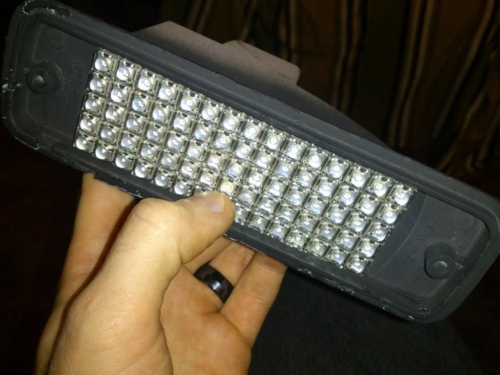
The LEDs I bought handle 20mA and drop ~2V across each LED. So I am running 6 LEDs in series with a 100ohm resistor at the end. So each turn signal has 36 sets of these running in parallel. I found this fits perfectly inside the housing, right between the two screw holes. Each signal has 216 LEDs in it so you have some room for mistakes, but trust me, you do not want to fix any mistakes.
-Do this 36 times
Because of the limited space I chose to put the resistors on a separate board. The board I bought was 180 x 128mm, part # EXPBRDLGPHEN and it was perfect size for all my needs. The LED array is 8 x 27. Here is how I laid it out:
The thing I like most about this layout is that all the LEDs face the same direction so it's easier to assemble.
There are 4 columns of 8 rows, and then the end has 4 groups of six LEDs.
I connected all the Positive leads using connector wire so that only one positive wire was going to the light socket in the housing.
Each negative lead MUST go to its own individual resistor, and then all resistors will go to the ground on the signal housing.


 Reply With Quote


 So I was wondering if going with straight resistor setup like yours is a good idea or do I need some kind of regulation circuit so they would last?


Bookmarks