
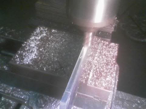
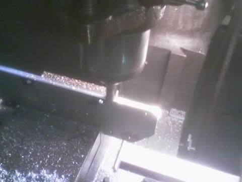
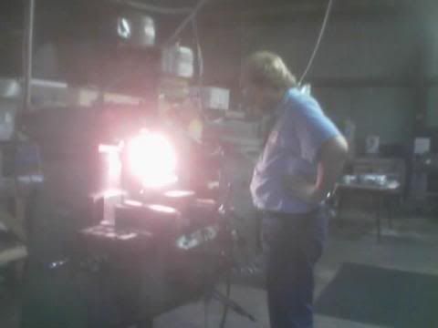
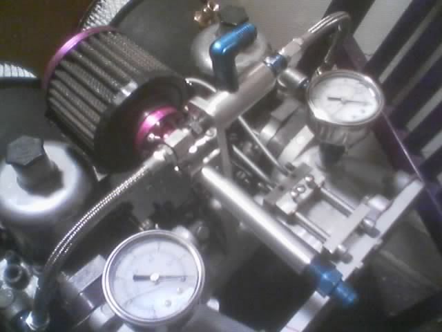
some random pictures from progress on the carb project today


some random pictures from progress on the carb project today

that is going to look how when it goes in Tim! and did u gian weight??? fatty..... j/k
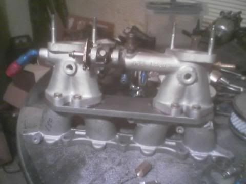
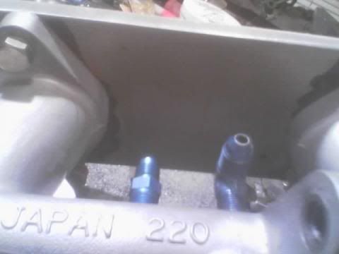
ports don't line up. are you going to address that issue?Originally Posted by lostforawhile
Alex.
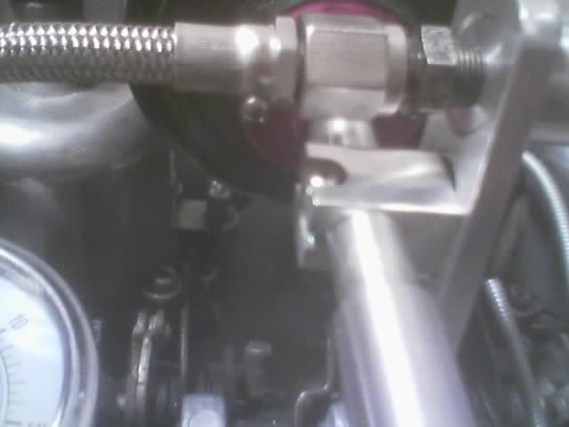
it's just sitting on there in the picture,they line up closer in the inside,the two outer ones are off a little bit,thats why the plate is so thick, I wanted enough material to be able to blend the ports together,once that plate is welded to the original manifold piece,I willl get in there with a pencil grinder and a flap wheel and blend them together. it's really hard to take a picture inside of the manifold.
are u going to dyno?
someday my california texas burger king whopper,someday LOL I better lose weight first or I'll mess up my dyno results,says this as eating choclate LOL
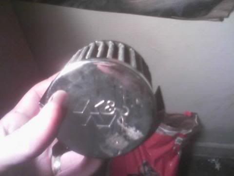
ok just have a few minutes,will get back with everyone tomorrow. a few pictures of the air cleaners being made. as of right now,one base is welded on,I'm waithing for a matching air cleaner to come in. tomorrow I'll solder up the base ring to the velocity stack to seal it,and hopefull the other air cleaner will come in then.
awsome man!

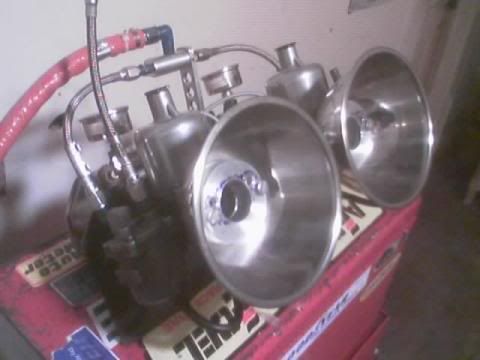
that is a big ass velocity stack

i hate to say this, but that's going to flow poorly. i'm hoping that you have provisions there for velocity stacks, because what i'm looking at is just an air cleaner. you have plenty of room for velo stacks, though.
http://en.wikipedia.org/wiki/Velocity_stack
Yeha he's right, also those flanges you have in the middle sticking up 1/2 inch are going to totally screw any decent air flow., but they look neat. Good luck with them!
I can't read the signature rules so MrBen deleted my signature.
they remind me of metal mixing bowls....
i'm thinking he's going to be bolting velo stacks to the flange there. that would be the only reason i'd use air cleaners that big.
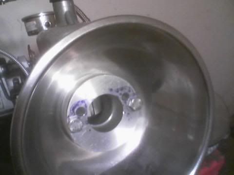
ok some explanations,sorry about the short post. the flanges in the middle will be tapered in the lathe, I'm just not done with them yet. the venturi on SU type carbs looks like a tube,not like a standard venturi. in stock form they just suck air in the end of the carb. I just wanted to make something kind of wild looking. I'm in the process of leading in the seam on the air cleaner flange right now. I think when they are done (and purple) they will be really wild looking. what the extra holes in the center piece are are the vents that go to the dashpot piston on the top of the carb. they are factory on the carb,thats how the entire principal of constant depression carbs works. I will find the url to the definition of the carbs in a little while,it explains them a lot better then I can. and yes they (were) mixing bowls, stainless steel is a bitch to work with also. I've seen parts on custom cars made from everything you can imagine. if it's the right shape for the parts you need ,run with it. LOL. I even saw a set of headlight buckets made from the same thing on a street rod,he had just frenched the light assembly into the bowl and polished it. looked for all the world factory.
ok here is the url, this explains how they work and also what the extra holes in the flange are for. http://en.wikipedia.org/wiki/SU_carburetor
as long as you taper that flange or what ever it is, it should work. try to find a way to get rid of that flange for a better flow. Also, are you going to use K&N filter or just regular paper shit?
Alex.
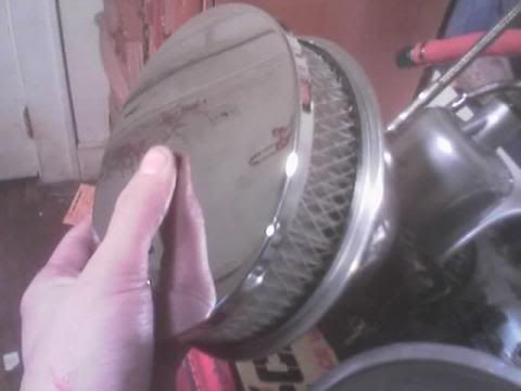
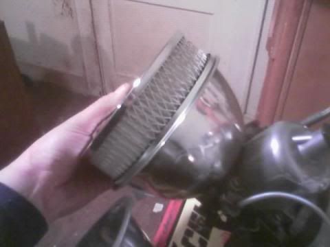
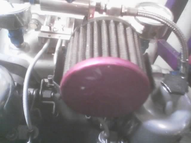
well I made those flanges because they are going to be turned into velocity stacks. that was the point of making them. on these carbs the air flows straight into a round untapered hole in front of the piston. any kind of flared area in front of it helps a lot in getting air into the carb. thats why those flanges are so thick,thats so I have enough material to machine the taper into them. these types of carbs respond a lot differently to air flow then a regular fixed venturi carb. remember the venturi in the carb gets bigger or smaller depending on engine demand. as far as filters for the moment I'll have the paper ones on here,then after everything is installed I'll get the K&n filters. this filter is a 6 1/2 X 2" the K&N filter is a 6 1/2 by 4" filter. almost 2 inches taller. there should be enough firewall clearance though. I had already measured from the back of the intake manifold flange to the firewall,before I even started this entire project.
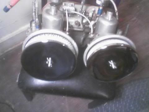
the bottom part of them dishes look like there the magnetic part trays u get a p-bo
1989 Accord Lx-i hatchback (current DD project)
1986 Olds Cutlass 442 clone (never ending project)
3Geez resident body man
Owner of Wreck-less auto body
hey, it's no problem using stainless bowls for that stuff. just make sure your wife doesn't find out :p.
i've looked for egg poachers to make some ghetto velo stacks. when some guys on honda tech compared their looks and general (not precise) measurements to $150 velo stacks, they compared quite well, at all of $1 each at wal-mart. of course they didn't flow like the real velo stacks, but for the price difference, you could spend the money elsewhere and make more power than "real" velo stacks.
I'm not worried about her finding out about the bowls,I got them for a dollar apiece. she helped hold the parts while I put the lead in the seams. she said if they were her bowls I would have been dead. the pieces at the bottom will be made into real velocity stacks. short ones,but read ones.
those are made from billet aluminum,they just aren't turned into velocity stacks yet is all. the extra holes are the passages that go to the dashpot piston on the top of each carb.the bottom part of them dishes look like there the magnetic part trays u get a p-bo
__________________
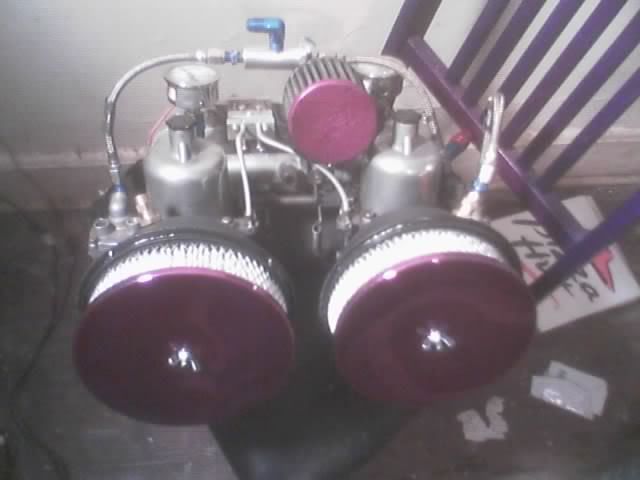
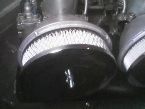
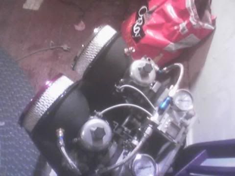
ok both air cleaner assemblies are finished,they look different in the pictures due to the fact that both identical air cleaner kits,had two different air cleaner elements. I'll fix that tomorrow. they aren't painted yet,this is due to the fact I need to weld on the fittings for the float bowl vents,and the two tubes for the pcv system fittings. the lead work came out pretty good around the seams,considering what i had to use .as far as equipment. the bottom picture makes it look like one air cleaner is off to the side,but thats just an optical illusion.
this picture you can see some of the seam work,that involved a lot of lead work,then media blasting,then more lead work to fill the gaps.
Last edited by lostforawhile; 01-31-2007 at 08:00 PM.
Interesting, now I know what a SU (Skinner Union) carburetor is. I seen one the other day on ebay. I had to copy & paste this, cause I seen this usefull on how the carburetor operates.
SU carburettors featured a variable venturi controlled by a piston. This piston has a tapered, conical metering rod (usually referred to as a "needle") that fits inside an orifice ("jet") which admits fuel into the airstream passing through the carburettor. Since the needle is tapered, as it rises and falls it opens and closes the opening in the jet, regulating the passage of fuel, so the movement of the piston controls the amount of fuel delivered, depending on engine demand.
The flow of air through the venturi creates a reduced static pressure in the venturi. This pressure drop is communicated to the upper side of the piston via an air passage. The underside of the piston is open to atmospheric pressure. The difference in pressure between the two sides of the piston tends to lift the piston. Opposing this are the weight of the piston and the force of a spring that is compressed by the piston rising. Because the spring is operating over a very small part of its possible range of extension, its force is approximately constant. Under steady state conditions the upwards and downwards forces on the piston are equal and opposite, and the piston does not move.
If the airflow into the engine is increased - by opening the throttle plate (usually referred to as the "butterfly"), or by allowing the engine revs to rise with the throttle plate at a constant setting - the pressure drop in the venturi increases, the pressure above the piston falls, and the piston is sucked upwards, increasing the size of the venturi, until the pressure drop in the venturi returns to its nominal level. Similarly if the airflow into the engine is reduced, the piston will fall. The result is that the pressure drop in the venturi remains the same regardless of the speed of the airflow - hence the name "constant depression" for carburettors operating on this principle - but the piston rises and falls according to the speed of the airflow.
.
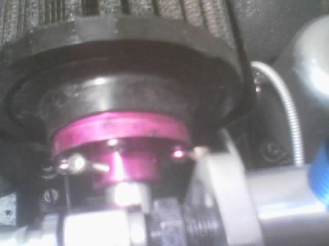
ok the air cleaners are finished,I painted them wih a wrinkle black finish,and the tops the purple that is on my engine. one top has to be painted yet,because I ran out of paint. there will be a lot of purpe on the manifolds when done,so the black accents will go with the purple.
air cleaner
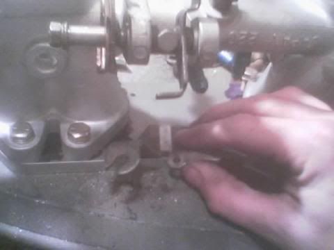
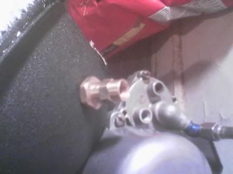
the fitting on the side is the vent from the fuel bowl. the fitting looks off because it's the wrong size adaptor,I was trying to figure out exactly where the hoses will sit. I have to order more -4 to 1/8 fittings.
[/i]the adaptor from the fuel bowl[/i]
I made these from barbed hose fittings with a pipe thread nut on the outside,and a male coupler. there is an o ring on the inside to seal the air cleaners. I cut off the barbs on the hose fittings so they wouldn't act like a siphon on the fuel bowl.
new breather
got this k/n breather for three bucks at the car show,I'm working on a trick way to mount it between the air cleaners,that will let me use the braided line coming off of the valve cover. the piece that fit in the grommet was damaged,so I will make a turned aluminum piece that screws to the inlet side of the breather.
Wow. You're really really creative. That's sick looking.
Alas, no more 3gee. She was a wonderful car and will be missed..
No more 92 hatch either! I go through cars too much.
90 CRX
OK the breather is done,this started as a three dollar used K&N breather from a junk pile at the car show.
breather after being media blasted and years on grime and grease emoved
the rubber piece that held the push on fitting was completly torn up,as well as the fitting was clogged. I sanded the rubber end of the breather flat and the first order of buisness was to make a mounting flange. normally it would have a shorter set screw,but I believe the cat ate the original one I had,so this is temporary.
the entire assembly consists of six pieces.
1. the filter
2. the mounting flange
3. the breather pipe that connects to the flange
4. the threaded end which is press fitted on to the breather pipe
5. the mounting bracket
6. the 1/4 npt pipe thread to -6 AN adaptor which will connect to my existing braided breather line
the mounting bracket. this attaches to the fuel rail support. I messed up several of these making them,including one that was perfect and I broke a tap off in it. that little square aluminum block took about 4 hours total time to get right
the filter itself,I have to redo the purple on the end,due to the fact i screwed it up.
 Posting Permissions


 Reply With Quote


Bookmarks